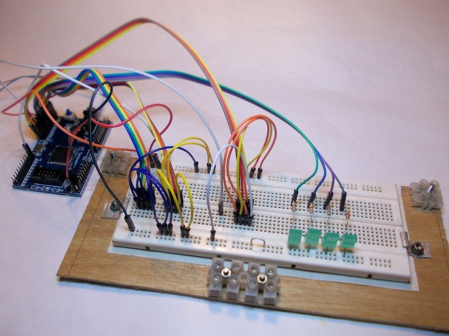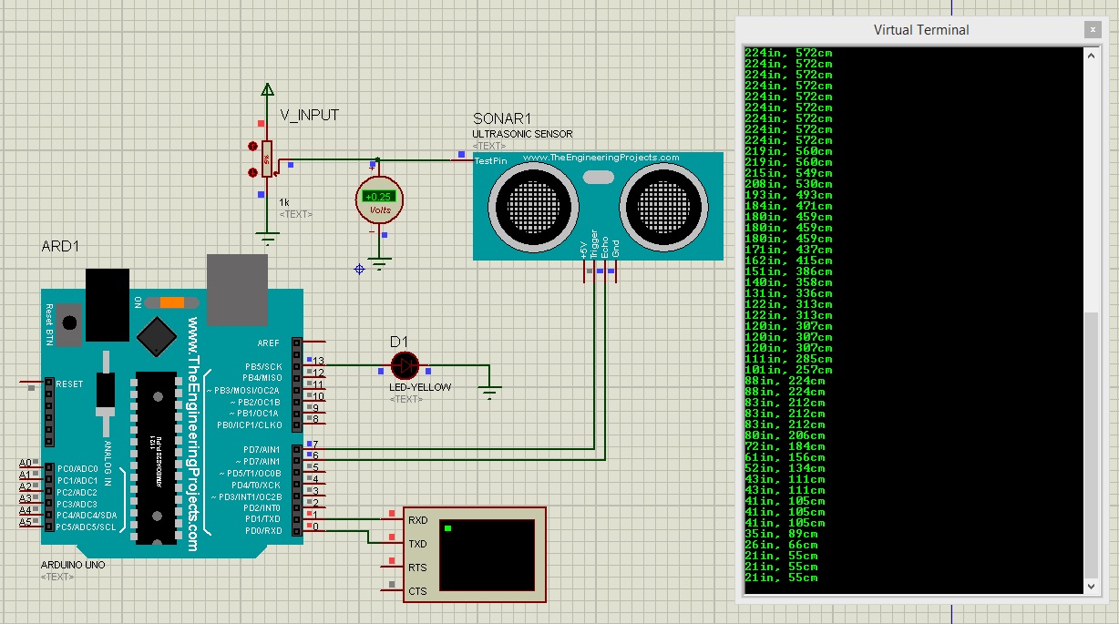
Among these simulation software, Proteus is my favorite one so let's get started with detailed Introduction to Proteus: Proteus, PSPice etc., before assembling them on actual hardware. Throughout our Engineering Course, we have to design a lot of electronics or embedded circuits and it's always a best approach to simulate these circuits first on some simulation software i.e. Today's tutorial is for beginners but still I would suggest you to read it once, as I am going to explain why Proteus? It's our first tutorial in Proteus series.

In today's tutorial, I am going to share a detailed Introduction to Proteus. As there is serious discussions going on about our previous Automatic LED Emergency Light Circuit using LM 317, Mr.Seetharaman has come up with a modified version of the same which answers many of the doubts raised in our Comments section.Hello readers, I hope you all are doing great. Note: Mr.Seetharaman has developed a new version of Automatic LED emergency light. Take a look: Simple Emergency Lamp Circuit This one is more simple,more efficient and uses minimum components. Here follows Seetharaman’s Description about the Modified Automatic LED Emergency Light using LM 317. Since there were lots of doubts from our readers on the LED emergency light, I have written a detailed letter to two of our readers. Of course few modifications are required, which I have indicated on the drawings and on calculations how I arrived at it. I thought of enclosing it to you so that it can be kept in some library of our site for any ones reference. For each circuit we can have a similar detailed theory, may not be with all calculation, just general operation theory of each part of the circuit. I have a feeling that most of the people would have made the mistake in base emitter of BD140, the lead out are against normal convention. To understand the above circuit in a better way, it can be divided into two parts.Ģ. The Battery charger circuit LED Lamp circuitġ. All are white hi bright LEDs rated for 3Volt 25mAĢ.

The total current requirement is 12 X 25 = 300mAģ. This current has to flow through T2 – BD140 PNP transistorĤ. The minimum current gain (hfe) of this transistor 500mA is 50ĥ. Hence the base current Ib requirement is Ic / hfe, 300 / 50 = 6mAĦ.


Base emitter drop of T2 at 500mA is 0.77 voltħ. With the fully charged battery at 6.9volt terminal voltage (for cycle operation use) the voltage available across the new bias resistance is (6.9 – 0.77)Ĩ. Hence the bias resistance is = 6.13 / 6 = 1000ohmsĩ. As the battery drains the final terminal voltage will be 5.4voltġ0. The bias resistance will be (5.4 – 0.77) / 6 = 770 ohms Hence a 680 ohms was preferred for bias resistance with drained battery also it will give enough brightness.ġ1.


 0 kommentar(er)
